
3.0. SEALING MECHANISM
If we want to create a pressure difference between two different areas in hydraulic systems, the necessity of sealing arises.
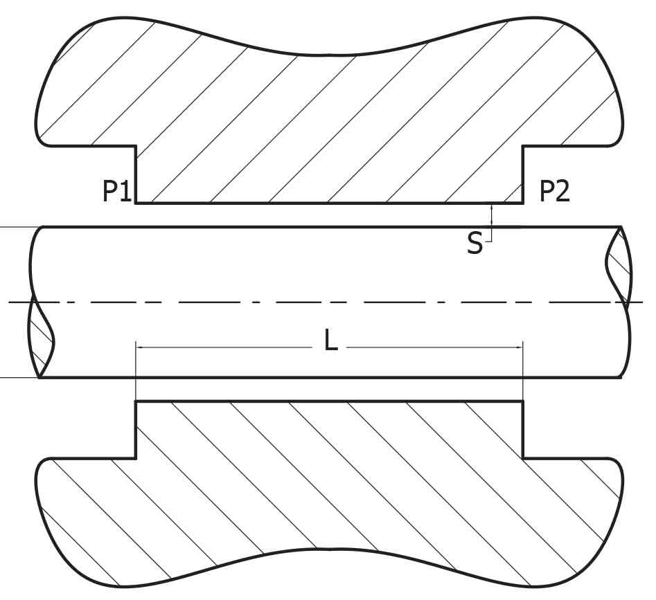
As seen in diagram-1, depending on the required pressure difference, a leakage occurs within the gap between rod and cylinder.
Where, pressure difference = ΔP
If ΔP =P1-P2
Q, the oil flow rate from ‘S’ gap, will be
Q = π.d. ΔP.S3 / 12.μ.L
Where, Q= Flow rate μ=Viscosity
In real applications, the “S” gap between both sides of the piston rod is not always equal. Due to radial forces there may be excessive contact on one side. This means that the the “S” gap will increase on one side.
If we look at the formula above, the “S” gap shows a twofold increase which is proportional to the cubed volume therefore resulting in an eightfold increase in passing oil rate. In practice, it is not possible to set the production tolerances of the “S” gap at zero.
Therefore, if a leakage is not desired, we are obligated to use a sealing element in this section.
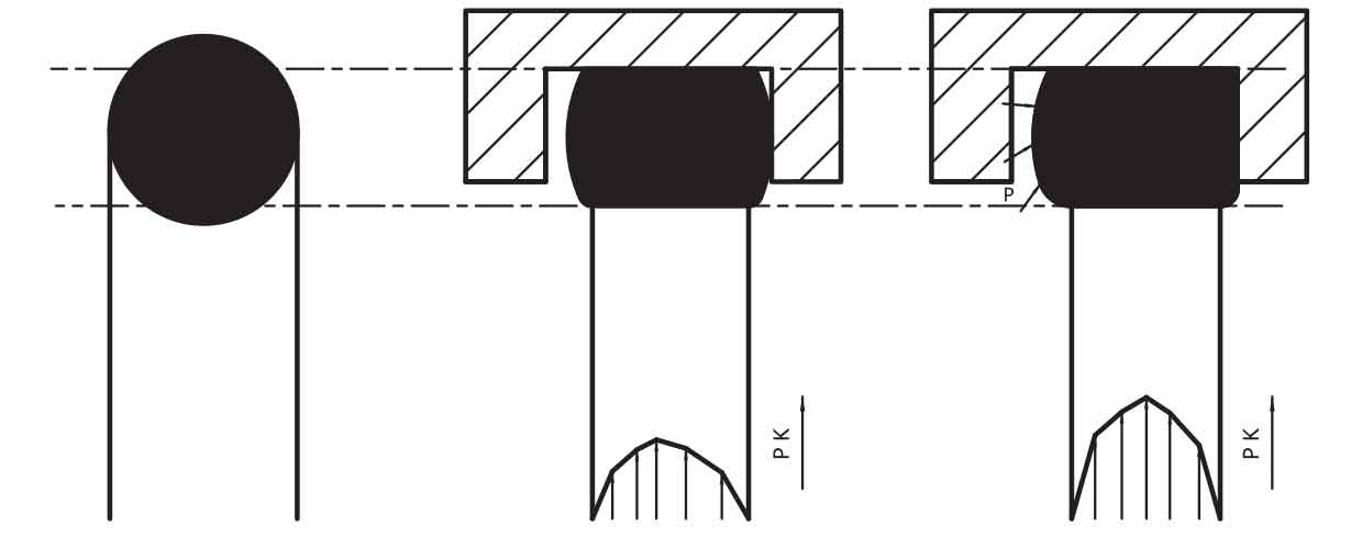
Seals made of elastomer materials are generally used in this kind of applications. When analysing the way in which seals work, we can see in figure-2 the logic behind the role of the O-ring. The O-ring illustrated in the diagram is depicted as being dynamic and functions as a rod sealing element. According to the general principle, after being fitted into the groove, a sufficient amount of space must remain in the groove.
When the system is in unpressurised condition, assembled O-ring, because of its design, applies a pressure on the Rod. We call this a pre-load. Pre-load is essential to provide sealing in unpressurised conditions.
When the system is pressurised, there must be a construction which allows the pressured media through as far as the sealing element housing. This pressured media which starts to fill the sealing element groove, leads to an increase in pressure force applied on static and dynamic surfaces by expanding the seal material. In this way, sealing is obtained.
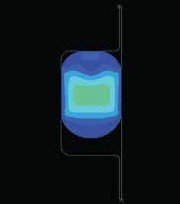
Below in figure-3 the result of fea (finite element analysis) can be seen. In this analysis, the working of an O-ring has been simulated digitally. The different colours used enable us to see clearly material deformation under critical loads.
We should not ignore the fact that this critical loads can increase and sealing materials can be viscosed i.e. there can be leakage problem because of the space on one side in the unpressurised part of the system. Therefore, seal manufacturers should show particular care when designing seals and hydraulic piston manufacturers should pay more attention in choosing the right seal product to improve the quality of their end product.
If there is not enough space between seal and groove, pressured media can’t expand the sealing element material which will cause excess friction forces and the seal will temporarily be deformed thus creating a leak.
3.1. STATIC SEALING
The increase in the contact pressure by the sealing element will reduce oil leaks in static sealing. Contact pressure in its optimum level will stop oil leaks completely. Of course in the meantime, an important factor which must not be ignored is the roughness of the application surfaces. Naturally, high roughness values require higher contact pressure.
Sealing materials will give different elastic and compression set results under different working temperatures. Therefore, Temperature differences may create really important functional differences. Low temperatures, in particular, may cause sealing materials to lose elasticity and become hard, resulting in the seal failing to work.
3.2. DYNAMIC SEALING
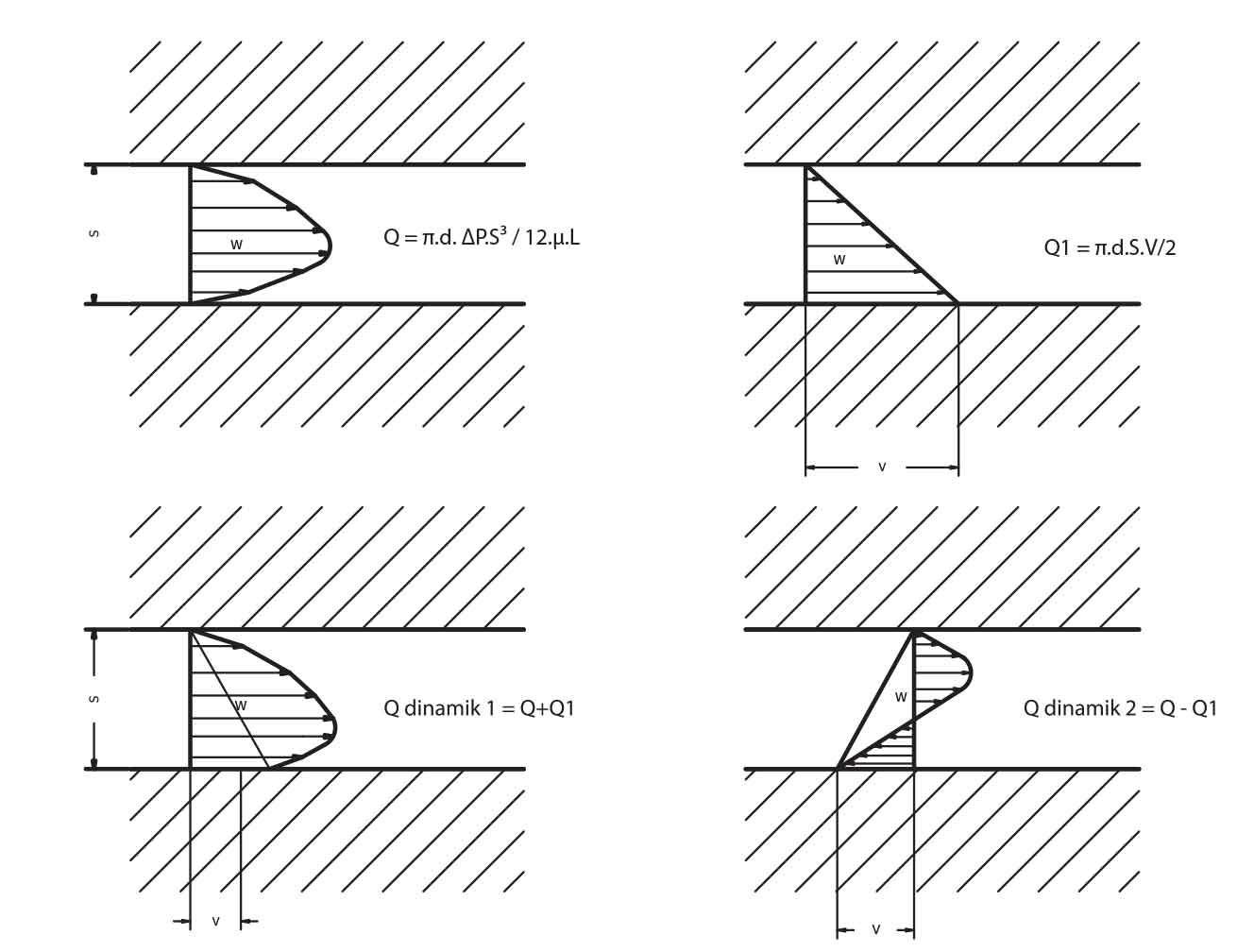
While we inspect dynamic sealing, we should look at the working principle which is explained by the flow formula;
Q = π.d. ΔP.S3 / 12.μ.L
In this formula, the rod is static and pressure is decreasing. If the rod is dynamic and pressure is not decreasing.
Q1 = π.d.S.V/2
Flow rate can be calculated with V= speed formula. If the piston is moving with the pressure direction, Q dynamic = Q+Q1
That is to say,
Q dynamic = π.d ( ΔP.S3/12. μ.L ± V.S/2)
In this formulation speed and direction of the speed will be of great importantance. On the other hand, if S gap is not parallel because of radial forces, extra pressure will be created locally (hydrodynamic pressure).
Because of this effect in microscopic size, force will be created in the hydrodynamic oil film between seal and dynamic surface. This oil film is only a few micron thick.
This oil film thickness is proportional to direction of the movement. Consequently, it is not possible to have leak free systems on dynamic applications. Nevertheless, oil film thickness can be decreased or increased depending on application type and seal geometry.
3.3. FRICTION FORCE
Friction force is not possible to be explained with classic friction force laws because of a slide on oil film thickness as explained above. 3 different friction forces occur because of the oil film:
1. Static (dry friction)
2. Mixed friction (dry and media friction)
3. Media friction (there is not any dry contact)
When the dynamic movement starts, a high friction force arises which leads to a mixed friction, resulting in the immediate decrease in friction force. After this, media friction i.e. a slide on oil film thickness begins. As the speed increases, so the friction force increases linearly.
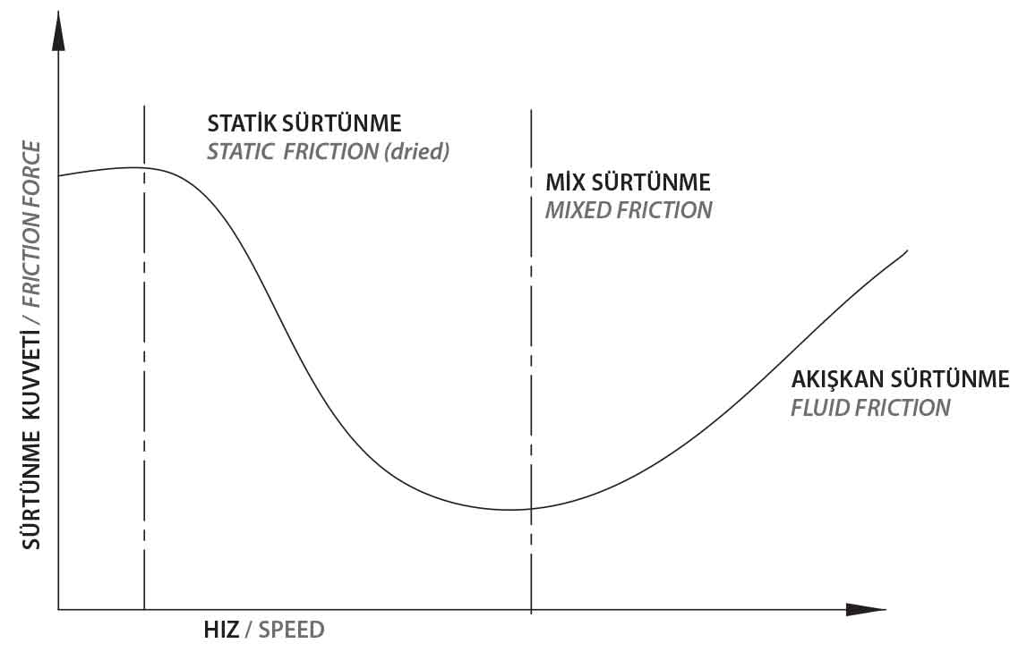
The oil film thickness is related to the system speed and directly to media viscosity. Two most important factors that affect the friction force are system pressure and temperature. Unsuitable friction forces create local high temperature and will result in seal failure and breakdown.
At the same time wear arises because of the tears in oil film thickness and with the effect of unsuitable surface roughness values, which results in leakage.